Virtual Local Area Network VLAN Tutorial
VLAN Introduction
“A virtual LAN (VLAN) is a group of networking devices in the same broadcast domain”
It is the concept of VLAN that most of the books are using but it doesn’t help us understand the benefits of VLANs. If you ask “What is a LAN?” you will receive the same answer: it is also a group of networking devices in the same broadcast domain!
To make it clearer, I expanded the above statement into a bit longer statement :)
“A virtual LAN (VLAN) is a group of networking devices in the same broadcast domain, logically”
It means that the devices in the same VLAN may be widely separated in the network, both by geography and location. VLANs logically segment the network into different broadcast domains so that packets are only switched between ports that are designated for the same VLAN.
Let’s take an example to understand the benefits of VLAN. Suppose you are working in a big company with many departments, some of them are SALES and TECHNICAL departments. You are tasked to separate these departments so that each of them can only access specific resources in the company.
This task is really easy, you think. To complete this task, you just need to use different networks for these departments and use access-list to allow/deny that network to a specific resource. For example, you assign network 192.168.1.0/24 for SALES and 192.168.2.0/24 for TECH. At the “Company router” you apply an access-list to filter traffic from these networks. Below is the topology of your network without VLANs:
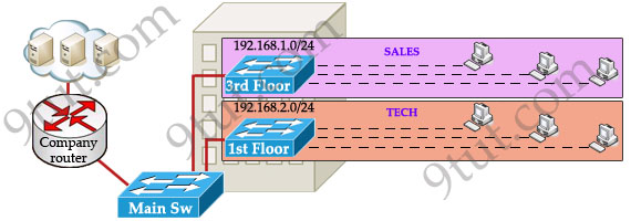
Everything looks good and you implement this design to your company. But after one month you receive many complaints from both your colleagues and leaders.
+ First, your department leaders need to access to additional private resources which employees are not allowed.
+ Second, the company has just recruited some new SALES employees but now the SALES room is full so they have to sit at the 1st floor (in the TECH area). They want to access to SALES resources but they can only access to the TECH resources because they are connecting to TECH switch.
To solve the first problem maybe you will create a new and more powerful network for your leaders. But notice that each leader sits at different floor so you will need to link all of them to a switch -> what a mess!
The second problem is more difficult than the first one. Maybe you have to create another network at the TECH area and apply the same policy as the SALES department for these hosts -> another mess in management!
Maybe you will be glad to know VLAN can solve all these problems. VLAN helps you group users together according to their function rather than their physical location. This means you can use the same network for hosts in different floors (of course they can communicate with each other).
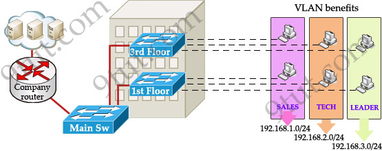
In this design:
+ you can logically create a new network with additional permissions for your leaders (LEADER network) by adding another VLAN.
+ employees can sit anywhere to access the resources in their departments, provided that you allow them to do so.
+ computers in the same department can communicate with each other although they are at different floors.
If these departments expand in the future you can still use the same network in any other floor. For example, SALES needs to have 40 more employees -> you can use 4th floor for this expansion without changing the current network.
But wait… maybe you recognize something strange in the above design? How can 2 computers connecting to 2 different switches communicate? If one computer sends a broadcast packet will it be flooded to other departments as switch doesn’t break up broadcast domains?
The answer is “Yes, they can!” and it is the beauty of VLAN. Hosts in the same VLAN can communicate normally even they are connecting to 2 or more different switches. This makes the management much more simple.
Although layer 2 switches can only break up collision domains but VLANs can be used to break up broadcast domains. So if a computer in SALES broadcasts, only computers in SALES will receive that frame.
So we don’t need a router, right? The answer is “we still need a router” to enable different VLANs to communicate with each other. Without a router, the computers within each VLAN can communicate with each other but not with any other computers in another VLAN. For example, we need a router to transfer file from LEADER to TECH. This is called “interVLAN routing”.
When using VLANs in networks that have multiple interconnected switches, you need to use VLAN trunking between the switches. With VLAN trunking, the switches tag each frame sent between switches so that the receiving switch knows which VLAN the frame belongs to. This tag is known as a VLAN ID. A VLAN ID is a number which is used to identify a VLAN.

Notice that the tag is only added and removed by the switches when frames are sent out on the trunk links. Hosts don’t know about this tag because it is added on the first switch and removed on the last switch. The picture below describes the process of a frame sent from PC A to PC B.
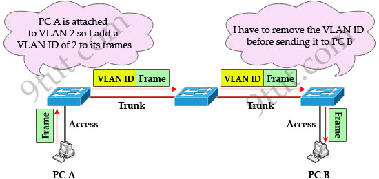
Note: Trunk link does not belong to a specific VLAN, rather it is a conduit for VLANs between switches and routers.
To allow interVLAN routing you need to configure trunking on the link between router and switch.
Therefore in our example we need to configure 3 links as “trunk”.
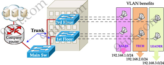
Cisco switches support two different trunking protocols, Inter-Switch Link (ISL) and IEEE 802.1q. Cisco created ISL before the IEEE standardized trunking protocol. Because ISL is Cisco proprietary, it can be used only between two Cisco switches -> 802.1q is usually used in practical.
In 802.1q encapsulation, there is a concept called native VLAN that was created for backward compatibility with old devices that don’t support VLANs. Native VLAN works as follows:
+ Frame belonging to the native VLAN is not tagged when sent out on the trunk links
+ Frame received untagged on the trunk link is set to the native VLAN.
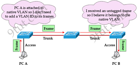
So if an old switch doesn’t support VLAN it can still “understand” that frame and continue sending it (without dropping it).
Every port belongs to at least one VLAN. If a switch receives untagged frames on a trunkport, they are assumed to be part of the native vlan. By default, VLAN 1 is the default and native VLAN but this can be changed on a per port basis by configuration.


Great work with excellent examples
I agree – Very helpful and understandable content!
Finally I understand this topic. Thanks for the examples.:)
Agree – Very helpful and understandable content! VerytoSeptember 26th, 2024