
Spine-Leaf Architecture Tutorial
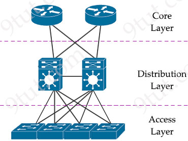
Spine-leaf architecture is a modern network topology widely used in data centers and cloud environments. It’s designed to offer improved scalability, high availability, and consistent low-latency communication. Unlike traditional three-tiered hierarchical networks (core, distribution, access layers), the spine-leaf architecture consists of only two layers of switches: spine and leaf switches.
|
Traditional three-tier architecture |
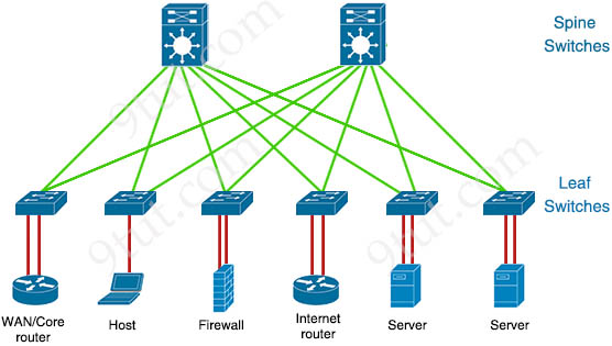 Spine-Leaf Architecture Spine-Leaf Architecture |
The spine layer consists of switches that perform routing and work as the core of the network. The leaf layer involves access switches that connect to servers, storage devices, and other end-users. This structure helps data center networks reduce hop count, reduce network latency and prevent bottlenecks, which are main issues of three-tier architecture.
Components of Spine-Leaf Architecture
As said above, the spine-leaf architecture consists of only two layers of switches: spine and leaf switches.
+ Spine Switches: These are high-speed switches that form the backbone of the architecture. Each spine switch is connected to every leaf switch in the network. The main function of spine switches is to interconnect the leaf switches and ensure data can travel between any two leaf switches with low latency.
+ Leaf Switches: Leaf switches connect directly to the endpoints (servers, storage devices, routers…) and to every spine switch. Endpoints communicate with each other via leaf switches, and traffic between endpoints on different leaf switches passes through one or more spine switches. Leaf switches are typically deployed at the top of the rack (TOR).
The following rules must be applied to spine-left architecture of each site:
+ Each leaf switch must connect to every spine switch.
+ Each spine switch must connect to every leaf switch.
+ Leaf switches cannot connect to each other.
+ Spine switches cannot connect to each other.
+ Endpoints connect only to the leaf switches.
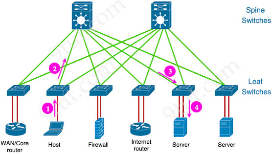
How Spine-Leaf Architecture Works
In a spine-leaf architecture, each leaf switch is connected to all spine switches, creating a full mesh between the leaf and spine layers. There are no direct connections between spine switches or between leaf switches. The key idea is that any traffic between endpoints connected to different leaf switches must pass through the spine layer. There are two types of traffic for this architecture:
+ East-West Traffic: When a server connected to one leaf switch needs to communicate with a server connected to another leaf switch, traffic flows up to a spine switch and then down to the destination leaf switch.
+ North-South Traffic: When a server needs to communicate with an external network (internet or WAN), the traffic typically flows through the leaf switches, which connect to the spine switches, and then to a gateway router.
Benefits of Spine-Leaf Architecture
+ Scalability: Since each leaf switch connects to every spine switch, adding more leaf switches (and thus more endpoints) doesn’t affect the performance. More spine switches can be added to increase bandwidth and support higher loads.
+ Predictable Latency: The architecture is non-blocking, meaning that every packet between any two endpoints takes the same number of hops (usually two hops: from leaf to spine, and back to leaf), so latency is lower and predictable.
+ High Availability: The full mesh connectivity between leaf and spine ensures redundancy. If one spine switch fails, traffic can still be routed through other spine switches.
+ Efficient Use of Bandwidth: The architecture uses Layer 3 routing such as equal-cost multipath (ECMP) routing so STP is no longer required, allowing multiple paths for traffic to be used simultaneously, balancing the load and preventing bottlenecks.


I think it’s important to point out that the connection between spine and leaf is L3 and the spine switches are running SVI’s. That is how come there are no L2 loops because the L2/L3 boundary is at the access layer running the default gateway for each access switch. As I understand it anyway.
good