Frame Relay – GNS3 Lab
In this article we will create a Frame Relay in GNS3 to learn how to configure Frame-Relay.
Note: If you need to revise your Frame Relay knowledge, we recommend you to read our Frame Relay tutorial first.
First we create 4 routers and link them as follows:
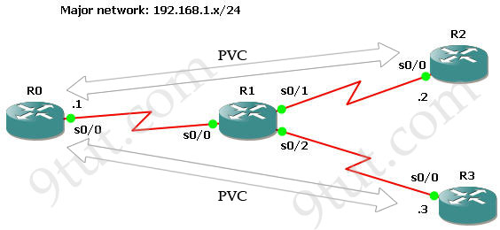
IOS used in this lab: c2600-bin-mz.123-6f.bin
Configure IP addresses
First we will assign IP addresses for all relevant interfaces. Notice that R1 will be Frame-Relay switch in this lab so its interfaces don’t need IP addresses.
On R0:
R0#configure terminal
R0(config)#interface s0/0
R0(config-if)#ip address 192.168.1.1 255.255.255.0
R0(config-if)#no shutdown
On R2:
R2#configure terminal
R2(config)#interface s0/0
R2(config-if)#ip address 192.168.1.2 255.255.255.0
R2(config-if)#no shutdown
On R3:
R3#configure terminal
R3(config)#interface s0/0
R3(config-if)#ip address 192.168.1.3 255.255.255.0
R3(config-if)#no shutdown
Configure Frame-Relay (using Inverse ARP)
To configure Frame-Relay on R0, R2 and R3 we need to enable Frame-Relay encapsulation and specify a type of LMI (ansi – in this case). Notice that Inverse ARP is enabled by default on Cisco routers so we don’t need to type anything to activate it.
R0,R2,R3(config)#interface s0/0
R0,R2,R3(config-if)#encapsulation frame-relay
R0,R2,R3(config-if)#frame-relay lmi-type ansi
Configure R1 as a Frame-Relay switch
In this lab R1 will be configured as a Frame-relay switch so no IP address is required.
Turn on Frame-Relay switching feature on R1:
R1(config)#frame-relay switching
On each interface we must specify how the frame will be proceeded. In practical, the Frame-Relay switch (R1) is placed at the ISP side so its interfaces should be set to DCE.
R1(config)# interface s0/0
R1(config-if)#encapsulation frame-relay
R1(config-if)#frame-relay lmi-type ansi
R1(config-if)#frame-relay intf-type dce //This command specifies the interface to handle LMI like a Frame Relay DCE device.
R1(config-if)#clock rate 64000
R1(config-if)#frame-relay route 102 interface Serial0/1 201 (will be explained later)
R1(config-if)#frame-relay route 103 interface Serial0/2 301
The command frame-relay route 102 interface Serial0/1 201 means frame-relay traffic come to R1 which has a DLCI of 102 will be sent to interface Serial0/1 with a DLCI of 201.
Note: Data link connection identifiers (DLCIs) are numbers that refer to paths through the Frame Relay network. They are only locally significant.
Continue configuring s0/1 & s0/2 interfaces (same as s0/0)
R1(config)# interface s0/1
R1(config-if)#encapsulation frame-relay
R1(config-if)#frame-relay lmi-type ansi
R1(config-if)#frame-relay intf-type dce
R1(config-if)#clock rate 64000
R1(config-if)#frame-relay route 201 interface Serial0/0 102
R1(config)# interface s0/2
R1(config-if)#encapsulation frame-relay
R1(config-if)#frame-relay lmi-type ansi
R1(config-if)#frame-relay intf-type dce
R1(config-if)#clock rate 64000
R1(config-if)#frame-relay route 301 interface Serial0/0 103
Use the show frame-relay map command to display the current map entries for static and dynamic routes
R0#show frame-relay map

By default, Cisco uses Inverse ARP to map remote IP address of the PVC with the DLCI of the local interface as we can see here. From the output above we learn that DLCI 102 is set on Serial0/0 of R0 and mapped with 192.168.1.2. The status of this connection is “dynamic” and “active”, which means it is operating correctly.
The outputs of this command on other routers are shown below:
![]()
![]()
Notice that you will only see the “map” at two ends. If we issue this command on Frame-Relay switch (R1 is this case) it will show nothing.
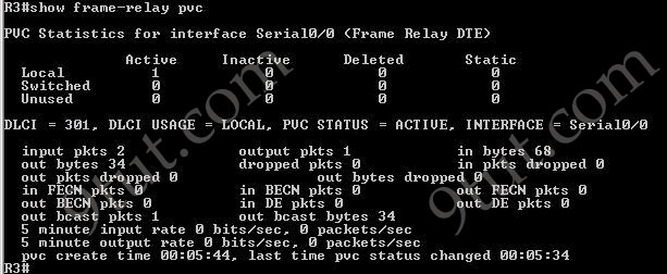
The show frame-relay pvc command is used to display the status of all configured connections, traffic statistics, BECN and FECN packets received by the router.
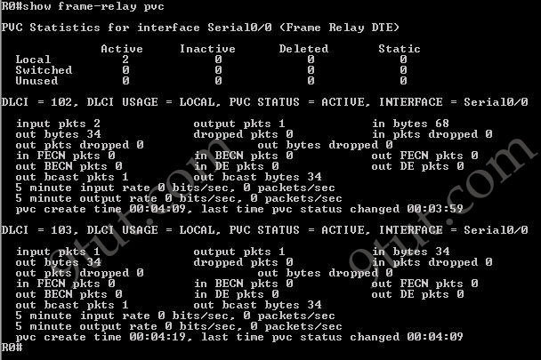

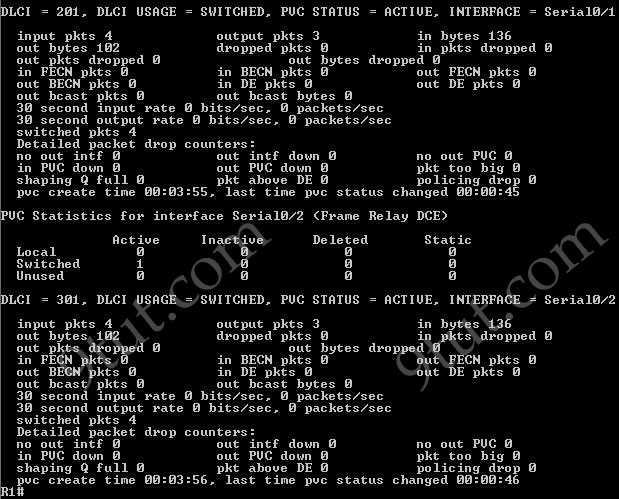
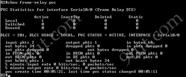
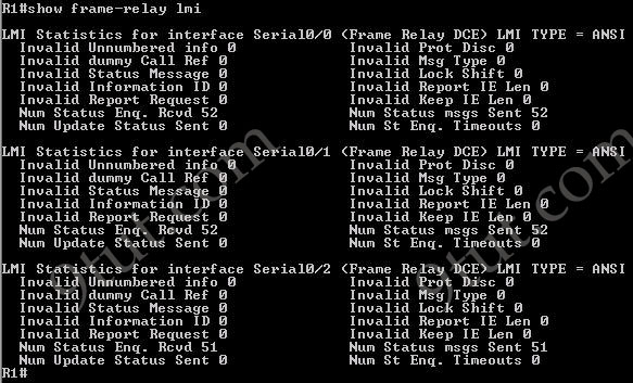
Use the show frame-relay lmi to display LMI traffic statistics (including LMI type, status messages sent and invalid LMI messages)



Pings from R0 to R2 & R3 are successful.


However ping from R2 to R3 is unsuccessful. It means that customers cannot see each other. This is because the split horizon rule: “A router never sends information about a route back in same direction which is original information came”. To overcome this problem we can configure subinterfaces on R0.


