Configure DHCP Packet Tracer Lab
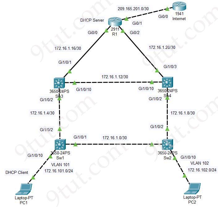
In this real world scenario, we will configure R1 as a DHCP server while Client 1 will be DHCP client with the topology shown below:

Note: If you are still not sure about DHCP, please read our DHCP Tutorial first.
You can download the Packet Tracer files here to practice (please unzip to use. You need Packet Tracer v8.1.1.0022 or newer to open it).
We will configure basic tasks (interface IP assignments, OSPF…) first on four switches and R1 with below configurations:
|
Sw1 Initial Config hostname Sw1 ! ip routing ! ip domain-name 9tut.com ! interface GigabitEthernet1/0/1 no switchport ip address 172.16.1.1 255.255.255.252 ! interface GigabitEthernet1/0/2 no switchport ip address 172.16.1.5 255.255.255.252 ! interface GigabitEthernet1/0/10 switchport access vlan 101 switchport mode access ! interface Vlan101 ip address 172.16.101.1 255.255.255.0 no shutdown ! router ospf 1 network 172.16.0.0 0.0.255.255 area 0 ! |
Sw2 Initial Config hostname Sw2 ! ip routing ! ip domain-name 9tut.com ! interface GigabitEthernet1/0/1 no switchport ip address 172.16.1.2 255.255.255.252 ! interface GigabitEthernet1/0/2 no switchport ip address 172.16.1.9 255.255.255.252 ! interface GigabitEthernet1/0/10 switchport access vlan 102 switchport mode access ! interface Vlan102 ip address 172.16.102.1 255.255.255.0 no shutdown ! router ospf 1 network 172.16.0.0 0.0.255.255 area 0 ! |
|
Sw3 Initial Config hostname Sw3 ! ip routing ! ip domain-name 9tut.com ! interface GigabitEthernet1/0/1 no switchport ip address 172.16.1.18 255.255.255.252 ! interface GigabitEthernet1/0/2 no switchport ip address 172.16.1.6 255.255.255.252 ! interface GigabitEthernet1/0/10 no switchport ip address 172.16.1.13 255.255.255.252 ! router ospf 1 network 172.16.0.0 0.0.255.255 area 0 ! |
Sw4 Initial Config hostname Sw4 ! ip routing ! ip domain-name 9tut.com ! interface GigabitEthernet1/0/2 no switchport ip address 172.16.1.10 255.255.255.252 ! interface GigabitEthernet1/0/3 no switchport ip address 172.16.1.22 255.255.255.252 ! interface GigabitEthernet1/0/10 no switchport ip address 172.16.1.14 255.255.255.252 ! router ospf 1 network 172.16.0.0 0.0.255.255 area 0 ! |
|
R1 Initial Config hostname R1 ! ip domain-name 9tut.com ! interface GigabitEthernet0/0 ip address 172.16.1.17 255.255.255.252 no shutdown ! interface GigabitEthernet0/1 ip address 209.165.201.1 255.255.255.252 no shutdown ! interface GigabitEthernet0/2 ip address 172.16.1.21 255.255.255.252 no shutdown ! router ospf 1 network 172.16.0.0 0.0.255.255 area 0 network 209.165.201.0 0.0.0.3 area 0 default-information originate ! ip route 0.0.0.0 0.0.0.0 209.165.201.2 |
INTERNET Router Config hostname Internet ! interface Loopback0 ip address 8.8.8.8 255.255.255.255 ! interface GigabitEthernet0/0 description Connected to R1 ip address 209.165.201.2 255.255.255.252 ! ip route 0.0.0.0 0.0.0.0 209.165.201.1 |
There are some facts in our topology:
+ Our PC1 (DHCP Client) was assigned to VLAN 101 on Sw1.
+ All four switches connected via Layer 3 interface with IP address assigned, not trunk links
+ OSPF was configured on all four switches and R1. R1 also sends its default route via OSPF (with “default-information originate” command)
Now we can ping among four switches and R1 to the Internet router successfully (8.8.8.8):
Sw1#, Sw2#, Sw3, Sw4#, R1# ping 8.8.8.8
.!!!!
Configure DHCP
Configure DHCP Pool on R1:
R1:
ip dhcp pool NETPOOL
 network 172.16.101.0 255.255.255.0
 default-router 172.16.101.1
!
ip dhcp excluded-address 172.16.101.1 172.16.101.3
With above configuration, we created a DHCP pool named NETPOOL and defined a subnet (172.16.101.0/24) that will be used to assign IP addresses to DHCP clients with the “network 172.16.101.0 255.255.255.0” command. A default-gateway of 172.16.101.1 (the IP address of interface VLAN 101 on Sw1) was also defined.
Finally, we also tells R1 that it does not try to assign IP addresses ranged from 172.16.101.1 to 172.16.101.3 with “ip dhcp excluded-address 172.16.101.1 172.16.101.3” command.
All the DHCP configuration was done but at this time PC1 cannot still receive IP address from R1. The reason is DHCP DISCOVER message is only broadcast in PC1’s subnet. Sw1 will not send this request to Sw3 so R1 cannot reply it.
Therefore we need to configure the “ip help-address” command under all Layer 3 interfaces on the way to the DHCP Server where the DHCP requests are received.
On Sw1:
interface Vlan101
 ip helper-address 172.16.1.17
On Sw3:
interface GigabitEthernet1/0/2
 ip helper-address 172.16.1.17
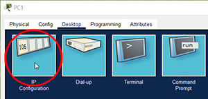
Now PC1 can get IP address via DHCP. Click on PC1 and choose “IP Configuration” box:

Choose “Static” option then choose “DHCP” option to reset DHCP process on PC1. A few seconds later, we will see a notification “DHCP request successful” and PC1 is assigned an IPv4 address of “172.16.101.4”. This is also the first usable IP address out of 172.16.101.1 to 172.16.101.3 range.

Access-list to permit OSPF and DHCP
In real world scenario, sometimes we want to block many types of traffic but allowing DHCP (and OSPF). Then we can use the below access-list on R1:
R1:
ip access-list extended INTERNET_ACL
permit ospf any any
permit udp any any eq bootps
permit udp any any eq domain
…(permit any other types of traffic if we need)


i can’t access my paid membership
@Ezra: Please send an email to support@9tut.com so that we can help you.
Gr8!
DHCP server
Thank you