Basic MPLS Tutorial
MPLS is a new forwarding mechanism called “label switching” in which packets are forwarded based on labels. However, hosts are unaware about labeled packets so routers will need to add a label when entering “MPLS area” and remove that label after leaving there.
The idea of label switching is to have only the first router do an IP lookup and assign a label, then all future routes in the network can “cheat” by doing exact match “switching” based on a label. This would reduce load on the core routers, where high-performance was the most difficult to achieve, and distribute the routing lookups across lower speed edge routers.
In a traditional IP network:
* Each router performs an IP lookup (“routing”), determines a next-hop based on its routing table, and forwards the packet to that next-hop.
* Rinse and repeat for every router, each making its own independent routing decisions, until the final destination is reached.
MPLS does “label switching” instead:
* The first device does a routing lookup, just like before.
* But instead of finding a next-hop, it finds the final destination router.
* And it finds a pre-determined path from “here” to that final router.
* The router applies a “label” (or “shim”) based on this information.
* Future routers use the label to route the traffic without needing to perform any additional IP lookups.
* At the final destination router, the label is removed and the packet is delivered via normal IP routing.
Therefore in an MPLS network, data packets are assigned labels. Packet-forwarding decisions are made solely on the contents of this label, without the need to examine the packet itself.
Cisco Express Forwarding (CEF) table
To enable MPLS on a Cisco router, we must turn on CEF first so let’s analyze what lies inside a CEF table.
As you know, router uses routing protocols (like OSPF, EIGRP, RIP…), static routes and connected routes to create the Routing table (or Routing Information Base – RIB). When CEF is enabled, the router uses this table to create a more optimized table, called Forwarding Information Base (FIB), which contains the next hop and outgoing interfaces of specific routes. Although FIB table does not differ much from RIB table but the router only spends very little time to find the correct entry, resulting in a smaller forwarding delay and more packets can be proceeded per second.
Below shows the topology of a small network and the output of the “show ip cef” command on R1 router.


CEF (FIB) table of R1
Of course CEF table is clearer than Routing table as you can see below

Routing table of R1
How MPLS forward packets
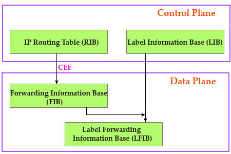
MPLS forwards packets based on the Forwarding Information Base (FIB) and Label Forwarding Information Base (LFIB) tables. FIB and LFIB have all necessary label information as well as the outgoing interface and next-hop information.
FIB: As said above, router uses CEF to create this table. In most cases, the ingress router uses this table for incoming unlabeled packets. The router matches the destination IP address to the best prefix (network) it has in the FIB. It then injects a label and forwards that packet.
LFIB: Used by the core MPLS routers (which are not ingress and egress MPLS routers). They compare the label in the incoming packet with the label they have in their LFIB. If a match is found, the routers forward that packet based on that match. If not, the packet will be dropped. The LFIB is created by the LIB and FIB tables.
Note: All routers in MPLS domain have both FIB and LFIB tables but only edge routers use FIB (ingress router uses FIB, egress router uses LFIB and FIB)

The LIB table holds all the labels known to the LSR and associated information that could possibly be used to forward packets. However, each LSR must choose the best label to use so FIB and LFIB contain only labels of best paths. To choose the best label, LSRs rely on the routing protocol’s decision about the best route.
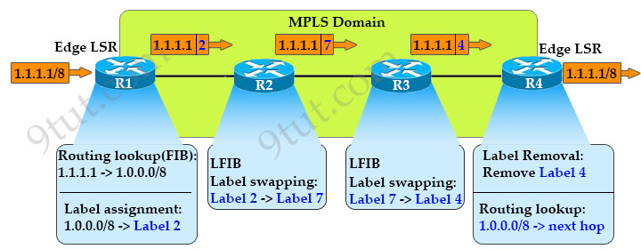
Label Switch Router (LSR) refers to any router that has awareness of MPLS labels, for example routers R1, R2, R3 and R4 in the below example. The entry and exit routers of an MPLS network are called edge LSR (or label edge routers – LER), which, respectively, inject (push) an MPLS label onto an incoming packet (label assignment) and remove (pop) it off the outgoing packet (label removal). An edge LSR is often a high-speed router device in the core of an MPLS network that participates in the establishment of Label Switched Paths (LSP) using the appropriate label signaling protocol and high-speed switching of the data traffic based on the established paths. In the below example, R1 and R4 are edge LSRs (LERs).
When a network’s inbound router receives traffic, it inserts an MPLS label between the IP packet and the appropriate Layer 2 header for the physical link. The label contains an index value that identifies a next-hop address for the particular LSP. When the next-hop transit router receives the packet, it uses the index in the MPLS label to determine the next-hop address for the packet and forwards the packet to the next router in the LSP.

In this example, when R1 receives a packet with a destination of 1.1.1.1 it first performs a routing lookup and assigns “label 2” to this destination and forwards it to R2. R2 checks its Label Forwarding Information Base (LFIB) table and sees that the “outgoing” label of label 2 is label 7. It swaps label 2 with label 7 and forwards it to R3. R3 acts similarly to R2 and swaps label 7 with label 4 and forwarding it to R4. The edge router R4 removes that label and does a routing lookup to find and forward that packet to its next hop. The whole process is summarized below:
1. After OSPF convergence, all routers have information about network 1.0.0.0/8 and this information is placed in the RIB.
2. On R1, the label distribution protocol (LDP) assigns the label 11 to the network 10.0.0.0/8 and advertises the label to its neighbors.
3. Other routers running OSPF also have information about this network so they use their own LDP to assign a label to this network. They also advertise it to other neighbors by using LDP. For example, R2 advertises to R1 (and R3) that it uses label 2 for the network 1.0.0.0/8. R1 receives this information and marks it as the outing label. R3 does not use this label but it also save this label in its LIB. R3 also advertises to R2 (and R4) it uses label 7 for this network. R4 advertises to R3 it uses label 4 for this network. Notice that labels are stored in the LIB.
4. Each router uses information about the network, local label and outgoing label to build the LFIB.
Now when an incoming packet to the destination 1.1.1.1/8 arrives, the ingress router lookup in the FIB table and it learns this packet should be labeled 2. The router pushes lable 2 to that packet and forwards it to the outgoing interface to the downstream router (R2 in this case).
R2 receives a labeled packet so it lookups in the LFIB, swaps the label 2 with label 7 and forwards it to the outgoing interface. Other core LSRs proceed incoming labeled packet in the same way as R2.
The packet continues traveling to the egress LER. Because egress LER receives a labeled packet so it lookups in its LFIB table too. In the LFIB, router R4 learns that label 4 is assigned to an implicit-null (or pop label) so the router removes (pop) the label and forwards that packet to the network 10.0.0.0/8.
That is all the theory. Now let’s return to our simple example with 3 routers to see what are actually inside these tables.


LIB table of R1

LFIB table of R1
MPLS key points
- Assignment of a particular packet to a particular FEC is done just once, as the packet enters the network.
- Packets are “labeled” before they are forwarded to the next hop.
- All forwarding is driven by labels.
- No further analysis of the packet’s network layer header at subsequent hops.
- Label is used as an index into a table which specifies the next hop and a new label. The old label is swapped with the new label and the packet is forwarded to its next hop.
It’s important to think of MPLS as having two components, the control plane and data plane. LDP is mainly used for the control plane to exchange labels. From the control plane we can build the data plane. On cisco routers this is CEF table.
Control plane: Exchanges Layer 3 routing information and labels; contains complex mechanisms to exchange routing information, such as OSPF, EIGRP, IS-IS, and BGP, and to exchange labels; such as LDP, and RSVP
Data plane: Forwards packets based on labels; has a simple forwarding engine


Please I need the latest dumps tosinosu at yahoo dot com.
hola ya esta disponible en esta pagina el cuestionario, para estudio de la certificación 2020 ccna 200-301. me gustaría saber
good
Please I need the latest dumps on 100 to 105 and 200 to 105 at saravanakumar1304 at gmail dot com
Thank you for the introduction to MPLS ! It helped me a lot to grasp the concept of MPLS !
Greetings, I noticed on the diagram that you have on this website that there is a sort of typo.
The diagram containing the control plane and data plane. On the data plain it has Forwarding Information Base as (LIB) when I think it should be (FIB). Correct me if I am wrong.
Thank you
@Just A Curious Tech Guy: Yes, thanks for your detection. We have just updated the figure.
@9tut,
In the first bullet point in the “MPLS Key Points” section, it says “Assignment of a particular packet to a particular FEC is done just once, as the packet enters the network.”
Did you mean to say “…packet to a particular CEF is done just once…” and not “FEC”. I searched the tutorial and could not find what “FEC” stands for. I google searched FEC in Cisco and found “Forward Error Correction”, but that doesn’t seem to apply (unless I’m mistaken?).